Saturday 15 November 2008

SAFETY INSPECTION ON 11-KV SYSTEM (Part 2)

Regulations 66 of Peraturan Elektrik 1994 stipulates that Safety Inspection on electrical installation which receives electricity supply rated more than 100A from Supply Authority (other than domestic installation) need to be inspected by competent person at least once a month (those with stand-by generators). Thus, every electrical installation should be kept in a tip-top condition to ensure security of supply and safety of personnel operating the installation. An air base is one of the critical installations which should be well-maintained as it is very critical to protecting country's sovereignty.
Recently I visited one of the 11-kV installations maintained by JKR. The visit was arranged to guide or enhance the capability of JKR Electrical Personnel in carrying out Safety Inspection works on electrical installations maintained especially the high voltage system.

As the exercise took only about four hours, we had only minimum time to inspect and conclude on the findings. Append below are some photographs taken at site during the inspection for reference. The remarks are purely personal and if anyone needs any further information, please contact the author.


Kota Bharu..

Friday 24 October 2008

SAFETY INSPECTION ON 11-KV SYSTEM (PART 1)

Safety Inspection on electrical installation which receives electricity supply from Tenaga Nasional Berhad (TNB) or other supply authorities in Malaysia through a circuit breaker more than 100A (other than domestic installation) is mandatory. This is clearly stated in Clause 66 of Malaysian Electricity Regulations 1994 which is to be read together with Electricity Supply Act of Malaysia 1990 (Act 447).
The Competent Person, Duties of Inspectors and Frequency of Inspection on the installation are stipulated in Clauses 67, 68, 69 and 70.
Recently, I had an opportunity to carry out safety inspection on an 11-kV installation together with Engineers, Technicians and Chargeman from JKR Elektrik Selangor.
Append below are some of the findings which I like to share with others on the observation and actions to be taken to overcome the shortcomings.


Photo 1A
The VCB truck has been removed for maintenance. The barrier provided for is inadequate to prevent access by unauthorised person. Accident could happen by just lifting the shutters (yellow & red) and exposed oneself to the live 11-kV busbar/cables behind the shutter. No warning notice was erected.
Solution :
The bus bar and circuit/cable shutters (photo 1B) should be locked. VCB opening should be blocked by using a bigger cover with DANGER and WARNING signages posted on it e.g. BAHAYA, JANGAN HAMPIRI PANEL INI..

Photo 1C
The RC slabs of cable trench cover are broken and sharp concrete left-over are risk to personnel especially at night.
Solution :
The trench could be filled up with sand and rendered with a thin layer of plaster at the same floor level. This will enable future access to the trench should a new circuit to be added.

Photo 1D
The First Aid Chart displaying The Holgger-Nelson's treatment method has been banned by the International Red Cross Society.
Solution :
A new first aid chart describing Cardiac Pulmonary Resuscitation (CPR) shall be installed to replace the existing one.


Observation :
2A & 2B - missing screws to the 11-kV panels need to be replaced immediately and URGENTLY. This is because, the panel has been designed equipped with the necessary screws to prevent the panel from being thrown out during untoward accident.
2C & 2D - DC supply system is very critical to the safe operation of high voltage equipment. DC is used to power up tripping coil of circuit breaker (open the circuit breaker during fault or when required), power supply to protection relays, etc. As such, DC supply system must always be made available to the panels and it must be maintained properly. Every care must be takento keep the DC system in tip-top conditions by following maintenance schedule recommended by the manufacturer.


Observation :
Switchgear labelling may seems trivial to some but actually it could cause unnecessary lost of lives if it is taken for granted.
Switchgear labelling must at all times be correct and updated immediately if necessary because the label on the panel is always referred to during any activity involving the panel (data-taking, switching, maintenance, replacement, etc). Wrong labelling on the panel could cause wrong switching to me made which may result in accident or lost of power supply. As such, the labelling on the panels must always be determined, updated, corrected and concise to ensure all activities carried on on the panel is always right and accident-free.


Observation :
4A & 4B - show the readings displayed by the respective ammeters and voltmeters of the incoming supplies (no. 1 and 2) from Tenaga Nasional Berhad. The ammeters show that the two incoming feeders from TNB are carrying 40A and 160A respectively.
From those readings, the Maintenance Engineer should always try to balance-up the two feeders as close as possible. This will ensure that both feeders are almost equally loaded and should one of the feeders experiences a power disruption, only about 50% of the installation is effected. If the shown readings are left unchanged and should the higher-loaded feeder experiences a fauly and trip, 80% of the installation load will be disrupted.

Observation :
Gauge 5A shows that there is still gas in the tank while gauge 5B shows that the gas has totally discharged from its tank. Maintenance personnel shouls always check that the gas content of the appropriate fire fighting system must always be made available to face any unwanted accidental fire so safe guard the installation.
Temperature gauge of 5C shows the oil temperature recorded of an oil transformer. This temperature gauge also acted as an Alarm and Trip protective device that will permit or stop the flow of current into the transformer depending on the condition of the transformer temperature. So, every gauge function must be fully understood by the maintenance personnel so that a right and prompt decision could be made to ensure the availability of power supply to the installation is always safely maintained.


Saturday 20 September 2008

T & C OF HT EQUIPMENT AT USIM NEW LIBRARY SUB-STATION


Views of USIM new Library Building - almost ready to
be commissioned and used (19-Sep-2008)

Universiti Sains Islam Malaysia (USIM) new library building construction started about two (2) years ago and now it is in the final phase of construction. Located on a hill behind Computer Science Faculty, the building will be another landmark of USIM campus.

Incoming 11-kV cables to feed electricity supply
to the sub-station no. 9 (Library)

The building electricity power supply is fed through Pencawang Elektrik No. 9 (PE09) which houses circuit breakers, step-down Cast Resin transformers and Low Voltage Switch Board. The power supply is also back up by a stand-by generator set. As the building M&E equimpent and services are almost ready to be tested and commissioned, its electrical infrastructure contractor is also busy completing the installation. The pre-testing and commissioning of sub-station equipment are being carried out by the Electrical Service Contractor engaged by the electrical contractor who was awarded the job via an open tender system.

All the 11-kV system for the building which comprises of 11-kV power cables, vacuum circuit breakers (VCB), 2 x 750 KVA 11/0.433-kV transformers must be fully tested before putting them into service. The operation of the VCBs can be carried out via Remote Control Panel (RCP) and the transformers are protected by Digital Temperature Relays. The VCBs are also equipped with Schneider SEPAM 1000+ OC/EF relays.

11-kV Vacuum Circuit Breaker at sub-station no. 9 (Library)

750KVA 11/0.433-kV Cast Resin Transformer

The following Basic Site Tests are being carried out on the high voltage equipment BEFORE they are put into service :

A. 11-kV Underground Cable - Insulation, phasing & Pressure Test (AC - VLF);
B. VCB - Insulation(1), Vacuum Check, Pressure Test, Insulation Test(2). Check on limit switches, tripping coil, heaters, meters, indicators, etc.
C. Transformer - Insulation and Ratio Test, Temperature Relay tests (Alarm & Trip)
D. RCP - Operation and status of VCB and Earth Switch.
E. Earthing/Grounding Test - ensure low Earth Impedance on Main Earth Bar and Transformer Star Point earth;
F. Protection Relays - CT Tests and SCIT Tripping Test;
G. Safety Clearances of all HT cables, transformer housing, terminations, etc.
H. DC Supply System - battery voltage, charger and capacity.
I. Others : Rubber mat, as-built drawing, Danger sign, No-Entry sign, CPR Chart, No Smoking sign, vermin-proof netting, cable trenches, trrench covers.

Once the Service Engineer has verified that all equipment tested are safe to be energised (via Form H), the HT equipment (all initially in OFF state) will be energised to receive electricity supply in the following Switching Sequence :

1. Switch ON supply from existing sub-station to the Incomer VCB (OFF position);
2. Verify 11-kV Voltage
3. Switch ON Incomer VCB (VCB 9B);
4. Verify voltage on busbar
5. Switch ON VCB 9C
6. Verify outgoing cable is energised;
7. Switch ON supply to Transformer No. 1 (VCB 9A)
8. Verify Voltage and Phase Rotation at LV Board;
9. Switch ON supply to Transformer No. 2 (VCB 9D)
10.Verify Voltage and Phase Rotation at LV Board.
11. Subsequent switching on LV Board will then be carried out.

1 - Potential Transformer; 2 - VCB Panel Heater
3 - PT HT Fuse; 4 - Relay and Panel Accessories


11/0.433-kV Cast Resin Transformer & Temperature Relay

BBNilai..

Monday 15 September 2008

KOMTAR JB - SEPTEMBER 2008 STATUS

The KOMTAR Upgrading Project Team ...


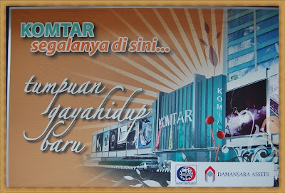
Advertisement on New Faces of KOMTAR JB as pasted on the Bill Board Hoardings :


The building contractor had entered the project site in November, 2007 and the project is supposed to be completed by May, 2009. Fortunately or unfortunately, at the midst of the construction, it seems that the owner has discovered that for the project to be certainly viable, bearing in mind that an investment of about RM 50 million has been allocated for the upgrading project, the podium section will be increased or catered for 6-storey building, instead of just 3-storey originally.

With the new decision, the demolishing area on site has been increased and consultants/designers of the podium block has been requested to re-check and ammend/update/redesign the building to include the next three stories which are mainly car parks. With the decision also, the floor-to-ceiling height of the first floor has been increased to cater for the M&E services and to create ceiling space especially for the big supermarkets.

So, the final status whether the new portions of the block will be constructed concurrently with the exisiting Phase A project will only be known on the 18-September, 2008 where the Johor Corporation Board Meeting will be held.

Photographs below show the status of construction today (15-09-2008) ...


Johor Bahru .. 15_09_2008

Sunday 31 August 2008

NEW UTHM LIBRARY TAKING SHAPE


The Main Library Building from Utility Block (M&E Services)


Universiti Teknologi Tun Hussein Onn Malaysia (UTHM), Batu Pahat is constructing a new 6-storey cylindrical block to house its Main Library. The block will also house six Lecture Theatres (to accommodate a total of 1,000 students), Vice-Chancellor Office and other administration offices.
The building is being constructed by Pembinaan Hamid-Ecovest Construction JV Sdn. Bhd., an established Design-and-Build Contractor in the country. The consultants involved inthe project are :
1. Juhari Hashim Architect (Architecture)
2. SAFF Consultants (Mechanical & Electrical Engineers)
3. Kristal Padu Sdn. Bhd. (Quantity Surveyor)
4. Civil & Structure Engineers
5. AV Consultant
6. ICT Consultant
7. Landscape Consultant

Recently on the 20-August-2008 (20-08-2008), I managed to visit and inspected the site. The new building is taking shape and the construction has reached the second (2nd) floor.
It is hoped that the building will be completed on-time to provide a modern and up-to-date library facilities to the students and surrounding community.


AFK_Skudai

Friday 29 August 2008

UPGRADING 11-KV SUB-STATIONS AT UTHM


Unloading of 200mm x 200mm RC Pile from Lorry at SSU 1

The upgrading works on 11-kV system at UTHM has been awarded to a cloass 1 Electrical Contractor at a cost of about RM 6.7 million. The works comprises of building a new Switching Station No. 1, constructing two new 11/0.433-kV sub-station buildings, upgrading the existing TNB sub-stations and supplying the 11-kV and 415-V related electrical equipment required in the SSU1 and sub-station buildings.

Unloading of 150mm x 150mm RC Pile from Lorry at PE 02

Today (29-08-2008), two lorry loads of RC piles have been delivered to site by the contractor. The setting out of SSU 1 and PE 02 had been confirmed by UTHM and the piling work will start very very soon.


With the initial commitment shown by the contractor, we hope the project could be completed ahead of time so that the activities and programs arranged by the UTHM could be carried out smoothly without any problem or shortcoming.

BPahat/Skudai

Monday 25 August 2008

NEW CHILLERS TO BOOST USIM A/C PLANT ROOM


USIM Central Utility Block No. 1 which housed 2 x 400 TR was commissioned in 2006 to supply chilled water to the Administration Block and Pusat Teknologi Maklumat.

Recently, the plant has been upgraded with the additional 3 x 400 TR Chillers which were successfully commissioned. This has increased the plant capacity to 2000 TR which will be used to feed chilled water to the new faculties under construction i.e Fakulti Quran & Sunnah (FQS), Fakulti Ekonomi dan Muamalat (FEM), USIM Main Library and Students Affairs buildings.

Due to very high starting currents of chillers (and compressors), Variable Frequency Starters or Soft Starters (SS) are used in the Chiller Control Panel. The starters (Danfoss) are used to limit the starting currents at a known period and are co-ordinated with the protection relays to prevent tripping of breakers during starting. The relay characteristic curves need to be changed from the normal IDMT Standard Inverse to the IDMT Long Time Inverse at the Circuit Breakers before the SS.

The plant is also equipped with the latest Building Automation System (BAS) whereby the chillers could be remotely monitored and controlled.

BBNilai